
THE IMPACT ON LIGHT AVIATION
The CEP design uses two independent motors to drive two independent fixed pitch propellers. An aircraft fitted with the system immediately gains twin “engine” status with all the benefits to flight safety and airspace accessibility.
The reverse thrust feature offers astonishing emergency and short field landing capabilities and extreme manoeuvrability in flight to suitable types of aircraft.
The system is immune to pressure altitude and icing conditions and therefore no mixture, manifold pressure or temperature controls are required greatly simplifying aircraft operations. No warm up or cool down procedures are required and RPM changes are rapid on command.
THE CEP DESIGN
The first contra rotating propulsion system (CRPS-225) being built by CEP is rated at 225kW/300hp. The complete self-contained nose assembly including batteries weighs 265kgs.
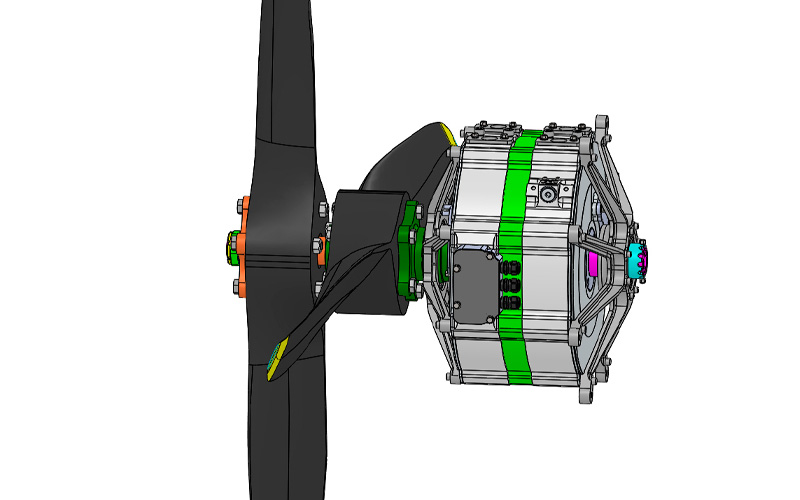
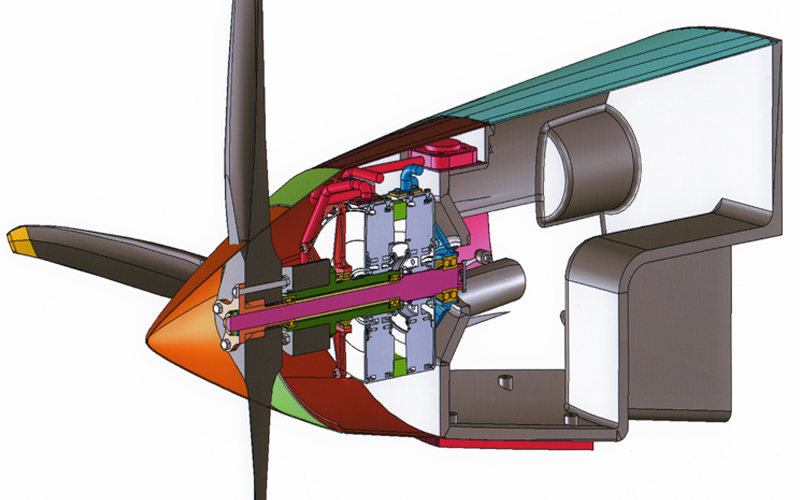
The basic components and layout are illustrated in Figure 1 below.
The illustration shows the twin motors, propellers, cooling arrangement and pipework, mounted to the carbon composite structural battery box. The batteries, inverters and controllers have been removed to more clearly show the battery box structure. The rear of the box bolts directly to an aircraft fire wall. A firewall mounted connector panel passes all propulsion control and management data via a cable to the cockpit.
The basic components and layout are illustrated in Figure 1 above.
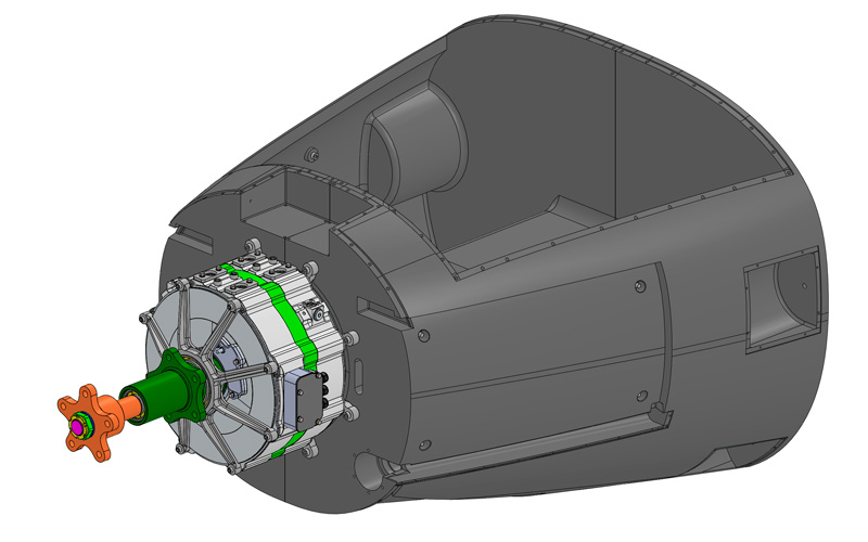
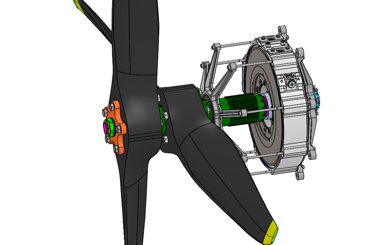
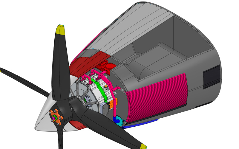
Figure 2 illustrates the motor assembly mounted to the front of the battery box. The propellers and cooling system have been hidden to show the arrangement more clearly.